This article outlines a walk-through on how to make your own Arduino board (even if you have not studied electrical engineering – but you may get yourself familiar during the progress).
Step 1: Start with building a rough prototype
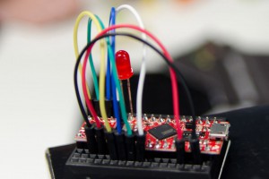 If you have just an idea or even a detailed concept, try to build a first prototype. Regardless if it is bulky or even looks awful at first, it might help you to get a feel of how this thing should work and most important if it works at all.
Arduino Uno (or similar) and a standard breadboard will work just fine. If you already want to go smaller, there are plenty of smaller Arduinos and Arduino-campatible boards, like the Arduino Pro Mini or Micro, the Pro Micro from Sparkfun or the various Feather boards from Adafruit.
Step 2: Modify your prototype, create breakout boards

Maybe you are still missing a component that is not available or you want to use a similar component which you can’t buy broken out?
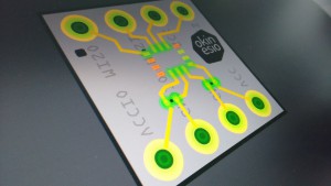
In our case, we had a breakout board for an accelerometer but we needed a different one. So we decided to make a breakout board for this specific sensor at first for testing and verifying its features.
The positive aspect about creating a breakout board is that you get to know the layout software, you build a board from scratch and go through the whole process without the need for complicated schematics etc.
Read your component’s datasheet to get the required pinouts, optional components and wiring needed.
Step 3: Make yourself familiar with a layout software
 Most Arduino(-compatible) boards provide the source files of layout (.brd) and schematics (.sch) in a format that was made with the EAGLE layout software. Technically you don’t have to rely on that specific layout software, but many open source manufacturers currently use it, so it will be the best choice for now and it’s freeware for makers and students (non-commercial).
It will in fact seem complex if you open it at first, but there are many tutorials about designing boards with EAGLE to get you started, e.g. tutorial at Sparkfun.com or tutorial at adafruit.com.
You could also craft your boards with Fritzing, as it is a user-friendly software for getting started with hardware layout. A big advantage using Fritzing is that you can directly order your PCB for a really good price – great for prototypes or small production runs (made in Germany – worldwide shipping).
Step 4: Creating your own board
 Now that you may be familiar with the basics of your layout software, we will create our own board.
Whether you need compact dimensions, a specific microcontroller or clock speed: In most cases you will save a vast amount of time and struggle, if you build on existing hardware layouts or at least get insights from existing schematics. It just will speed up your work and even your learning curve.
If you already experimented with a similar board while prototyping, then you could use the layout files and schematic (if available) as a starting point for your board and rework the file to meet your expectations.
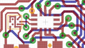
When you’re done with the electronic schematic (electronic diagram), you will draw the traces that connect all components according to your circuit on your schematic layout.
Sketching an electronic diagram and routing a board can be challenging at first if you don’t have the expertise, but there are plenty resources out there and the community you can ask. A great way to get to know experienced people is to visit one of the Makerfaire venues.
Step 5: Order your PCB (Printed Circuit Board)

When you layout is finished, be sure to check it again for possible mistakes (missing routes etc.) and send it over to your favorite manufacturer. They might accept the BRD-file from EAGLE or need the common used Gerber files.
You will save money, if your board can be placed on an existing PCB panel with standard parameters and if you don’t need your board the next day. An average delivery time when ordering this way might be approx. 10 to 20 days.
Hint: You can actually etch your PCB at home! This can come in handy if you only need one PCB and don’t want to wait that long. You can find tutorials on how to do this on Sparkfun, Makezine (a friendly one) or here (no-etch method).
These tutorials may vary in the way you prepare or mix the etchant solution (Use at your own risk!).
Step 6: Choosing the right components
While you are waiting for your PCBs to arrive, you can search all your components online that you specified in your schematic. This could be tricky because there are many manufactures that offer components with similar specs – try to get the most reliable ones for a reasonable price 😉 If you based your new layout on an existing schematic you might already find part names or order numbers annotated for that device.
Most popular shops for ordering components are Mouser, Digikey or Farnell. You can find almost anything there – that is definitely overwhelming at first. If you just need basic or common used components try one of the maker-friendly shops: Adafruit or Sparkfun.
Step 7: Assemble your board

Once your PCBs and components arrived, it’s time to assemble your board! You most likely will have SMD components, so you need to apply solder paste on your PCB first: Depending on your average pad sizes you possibly can do this with a solder paste syringe for each pad or you will be well advised to use a stencil to apply paste as it will be time-saving for multiple boards and more precise for pads with fine pitch.
There’s the thing: Most PCB pool manufactures don’t offer to include a stencil with your PCBs, so you need to order it additionally (if available anyway), which can be expensive in sum, if you only order a few boards. We would recommend to order a aluminum stencil if you order a larger amount of PCBs and know that your layout will stay this way, because it will make your assembling process more effective and less frustrating. Some of the advantages are that they allow a faster reset for applying paste to the next PCBs, they are durable through plenty applications and have sharp edges for accurate paste placement.
As stated above you might not get a stencil, so you need to make one yourself. If you have access to a laser or vinyl cutter (e.g. in a FabLab) this is your way to go. Otherwise you need to improvise and make our own stencil as explained here.
How to apply the solder paste? Here you go – this video even give you some advise on how to place components afterwards.
Tips for placing components:
- Be careful not to lose a component (they can be really tiny!)
- Place the smaller ones and the ones in tighter spaces first
- Do not apply to much pressure when placing – rest them firmly
- Verify the polarity for special parts (e.g. diodes, sensors, …)
Step 8: Reflow!

It’s baking time. The best way to do this on an acceptable budget with good results is to get a small pizza oven. You will need a temperature control unit that can heat the oven with a specific temperature curve that won’t damage the components while reflowing.
This oven and a controller like this, will do the job. There sure are more affordable controllers out there.
If you have the equipment, calibrate the control unit for your oven and place your boards inside. Then run the reflow process – and Voilà!
Attention: It’s HOT!
You should watch this excellent video by Dave from EEVblog on that topic.
Step 9: Flash the bootloader
It’s necessary that you flash your board, because your microcontroller comes blank from the distributor and needs a bootloader to function as intended. Therefor you need the common ISP or JTAG interface broken out on your board where the chip can be accessed for flash programming.
You will flash it with an Arduino-compatible bootloader that should also be compatible with your hardware. If it’s not compatible, you need to compile your own bootloader. So you should consider if you build your hardware on similar specifications based on an Arduino (and the corresponding bootloader) or need to modify an existing one.
Step 10: Be proud.
If everything has worked out so far and you flashed the device successfully, you are ready to program it with the Arduino IDE. Just choose your bootloader and upload your code.
Last check: Does every component work as expected (all pins connected properly)? If yes: Congrats – you’ve made it!